Abstract
In-line ultrasonic measurement of wall thickness has been
for many years a common quality-monitoring tool in medical
tubing extrusion, most commonly for medical applications
where documented quality is essential. Recently this measurement
technique has been applied to wire and cable jacketing, and
the significant material savings achieved demonstrate it
can provide an attractive return on investment. This valuable
tool can also be applied to many of the key constructions
in fibre optics technology, including tight-buffer, loose-tube,
and cable jacketing. This article reviews the fundamentals
of this measurement technique, the benefits to be expected
from its use, and various extrusion applications.
Introduction
Ultrasonic wall thickness measurement uniquely permits measuring
wall thickness at the beginning of the extrusion line, which
allows for optimum die centring by an operator. The real-time
display of the wall about the core immediately shows the
results of the centring effort, so that subsequent changes
can be made as needed to further optimise wall balance. Without
this capability, the manufacturer is dependent on sample
checking at the end of the line. Quite often, a manual change
to the die effects an over-correction and begins a process
of multiple changes which, though time-consuming, still yield
less than optimum result. Understandably, the operator may
eventually decide to “leave well enough alone”,
to the detriment of quality.
Beyond optimum die centring, measurement at the die also
promotes a much faster control response when the system is
set to control average or minimum wall thickness. Of course,
continuous wall thickness measurement also permits detailed
quality documentation as to other parameters.
Ultrasonic measurement basics
The basics of ultrasonic measurement (Figure 1) are readily
understood. An ultrasonic transducer contains a piezo-electric
crystal which, when hit with a voltage pulse of very short
duration, causes a sound wave to be created at the face of
the transducer. Depending on the shape of the transducer
lens, a shaped sound wave emanates from the face of the transducer,
through water, to the surface of the product to be measured.
A change in the speed of sound in water occurs when a material
with a different acoustic impedance from water is encountered.
This change causes a reflection back towards the transducer,
resulting in an interface “echo.” A portion of
the sound energy continues on into the material. When a subsequent
change in speed is encountered, a second echo is reflected
back to the transducer.
Figure 1: Ultrasonic measurement technique
An ultrasonic processor looks for these reflections (echoes)
and correlates the distance (t) between them to a wall thickness.
The quality or clarity of the echo is a function of the strength
of the sound wave to begin with, the degree of difference
in acoustic impedance between the two materials, and the
alignment of the transducer to the reflecting surface. Transducers
are generally very rugged, relatively low-cost devices with
long life expectancy. Their low cost facilitates using multiple
transducers for applications, which require multiple points
of wall thickness measurement. A wide range of transducer
constructions is readily available for customisation to the
product application as to wall thickness, resolution required,
and target (product) size.
Use of this technology calls for product immersion in water.
Unlike the low-frequency ultrasonic transducers used for
camera distance measurement, these applications require frequencies
in the 10 to 30MHz range which dissipate in air. They therefore
require water as a transmission medium. The range of transducer
types in routine use allows measurement of thickness from
0.02 to 50mm and beyond. Repeatability is on the order of ±0.001mm.
Applications
1. Tight-buffer
Application of ultrasonic wall thickness measurement to a
tight-buffer product is quite straightforward (Figure 2).
The relatively low line speed, line stability, and PVC-coated
fibre interface make for a very stable installation. Measurement
is done as close to the crosshead as mechanically practical
(Figure 4). Great precision can be achieved in measurement
of a 0.325mm wall thickness. A small, four-point sensor
assembly, similar to that shown in Figure 3, would be used,
often with guides to assure product centring within the
four-point measurement field.
Figure 2: Tight-buffer
Figure 3: Four-point ultrasonic sensor assembly
The sensor assembly shown has provision to raise and lower
the assembly as needed to facilitate product centring. As
with all ultrasonic measurement, the sensor requires submersion
to a point approximately 25.4mm above the tight-buffer.
Figure 4: Instrumentation on tight-buffer line
2. Loose-tube
Loose-tube production presents more of a challenge for ultrasonic
measurement. First, the wall interface between the PBT
tube material and the gel filling does not provide as strong
an interface as with other materials. This necessitates
taking some care initially to assure that the processor
is appropriately set-up to distinguish this interface.
Secondly, it is common practice for the product here to
be cooled gradually.
Figure 5: Loose-tube construction
The first 10 to 20 feet of “cooling” trough
may in fact employ a hot-water quench of approximately 57°C.
Subsequent cooling trough sections will have progressively
cooler water. Standard ultrasonic transducers are rated at
49°C and therefore are not appropriate for continuous
submersion in this hotter water. This can be circumvented
by positioning the ultrasonic assembly in the second section
of the cooling trough. While not ideal from the standpoint
of ease in die centring, it is still a reasonable trade-off.
Alternatively, high-temperature transducers may be used that
are suitable for continuous immersion in the hotter water.
Figure 6: Instrumentation on a loose-tube line
3. Jacketing
Fibre optic jacketings cover a broad range of sizes and applications
but all generally lend themselves to wall thickness measurement.
The outer jacket material (Figure 7) may be applied over
a host of surfaces, including metal and other blocking
materials.
Figure 7: Jacketed cable
The size range of the cable to be produced will dictate
the size of the sensor assembly employed and the number of
measurement points: four, six, or eight (Figure 8). A fixed
sensor assembly as depicted in Figure 5 is positioned just
after the crosshead in the first cooling trough.
Figure 8: Four-point cable sensor assembly
Figure 9: Instrumentation on a jacketing line
Again, provision must be made for assuring water submersion
to a point just above the face of the lowest transducer.
Note that, in this application, the measurement field for
each transducer is quite wide, enabling product position
freedom without compromising the measurement. This sensor
assembly (Figure 10) can be mounted in an existing cooling
trough, or the trough modified to accommodate it. Alternatively,
a custom trough section with sensor assembly may be supplied
for positioning at the entry to an existing trough.
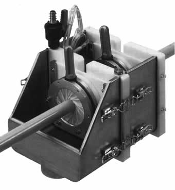
Figure 10: Custom tank with sensor assembly
Benefits
Once in-line wall thickness measurement is employed in these
applications, all the traditional benefits of gauging will
follow. Typically the wall measurement function is added
to a more common host processor that provides for the primary
instrumentation, including diameter measurement and fault
detection. Wall measurements and corresponding data collection
simply become integrated with these more common measurements.
SPC control charts, SQC quality records, and data archiving
are among the reporting capabilities. Standard trending and
tolerance alarms are also available to the user. Possibly
the chief benefit is more uniform die centring. What was
once a tedious chore becomes an almost effortless accomplishment.
Thickness control of average or minimum wall thicknesses
can be implemented, and significant material savings readily
achieved for jacketing applications.
Conclusion
Ultrasonic wall thickness measurement has proven itself
in hundreds of applications in both the tubing extrusion
and wire and cable markets. It can also contribute importantly
to the quality production and reporting needs of the fibre
optic industry, while at the same time delivering very attractive
returns on investment.
Zumbach Electronic AG
P.O. Box - CH-2552 Orpund
Switzerland
Fax: Int’l +41 32 356 04 30
E-mail: [email protected]
Website: www.zumbach.com
|


