Abstract
The enormous improvements in the optical fibre production equipment have been achieved by optimising each step of the production process. In order to increase the performance of the cable, to reduce the costs of the final product and to enhance the production range of the equipment, new technologies and devices have been invented to reduce optical loss, increase production speeds, reduce the set-up and down times of the line, reduce product scrap, and allow more production flexibility.
Introduction
Today’s fibre optical cable designs for stranded loose tube cable construction are based on plastic buffered tubes each containing 1 to 24 fibres. The plastic tube protects the fibres from lateral forces and the fibres have some space (controlled by excess fibre length) to move inside the tube when the cable length is changed. The tubes are filled with jelly to prevent water penetration into the tube, stranded around a strength member and sheathed to give the typical loose tube type cable construction shown in Figure 1.
Figure 1: SZ-stranded loose tube cable construction
It is important when the operating temperature is reached that both the length of the fibre and the tube are the same The performance will be the best when the fibres on the average are in the centre of the tube (Figure 1). When the cable is elongated the fibre will move towards the cable core, when the temperature decreases, the cable shrinks and the fibre moves outwards from the centre. When the cable has reached the allowed maximum shrinkage or elongation, the fibre will touch the tube wall causing increased attenuation.
High-speed buffering technology
Effect of different polymers
Polymers of different types or grades of the same polymer have different shrinkage behaviour. This arises from the difference in crystallisation kinetics of the materials (Figure 2).
 Figure 2: Crystallisation kinetics of PBT versus PP Figure 2: Crystallisation kinetics of PBT versus PP
During the loose tube production process, when the line speeds are increased the friction between the tube and the water will increase. When tubes are cooled down under tension the post extrusion shrinkage will be extremely high. This can lead to a higher excess fibre length (EFL) than expected. Therefore the construction based on a mid-span capstan can minimise the shrink back tendency in the finished product (Figures 3 and 4).
Figure 3: Effect of line speed on EFL
Figure 4: Effect of capstan position on EFL
The basic parameters in the buffering process for adjusting the excess fibre length (EFL) are:
- Fibre pay-off tension;
- Viscosity of jelly;
- Water temperature in the cooling trough;
- Position of the mid-span capstan;
- Tube tension between mid-span capstan and single wheel capstan;
- Tube tension between single wheel capstan and take-up;
- Tool design.
In additional to the above mentioned basic parameters the production speed of the buffering process and the crystallisation kinetics of the used tube polymer are key parameters to achieve the expected excess fibre length (EFL), production performance and product quality. Rosendahl has achieved high-speed buffering performance by using different type of tube materials for a variety of cable designs (see Table I).
Number
of Fibres |
2 |
6 |
12 |
6 |
| Polymer Type |
Spec. Polymer |
PBT |
PBT |
PP |
| Production Speed |
900m/min |
420m/min |
380m/min |
330m/min |
| EFL(%) ±0.03 |
0.05 |
0.05 - 0.3 |
0.05 - 0.3 |
0.15 - 0.5 |
Table I: Line speeds of different product designs
The latest in technology much as high dynamic fibre pay-offs, low friction cooling systems, driven adjustable mid-span capstan and automatic dual take ups are necessary for high production speeds.
Productivity
To offer solutions, which increases the Overall Equipment Efficiency (OEE) of the secondary coating line, Rosendahl has developed an active fibre launching system for continuous production.
Automatic fibre launching and fibre change over at production speed
Continuous improvements are essential to maintain the highest level of productivity for the cable manufacturing industries. To ensure a continuous process, a higher levels of automation are necessary. From conception through design of the new automated equipment, all aspects have to be considered to maintain the significant improvements in regards to velocity, flexibility and usability of the modern loose tube buffering line. Rosendahl has improved the line productivity by implementation of a fibre launching system “ChiB” in combination with a fibre clamping & cutting device.
Active launching system “ChiB”
Named “ChiB” the new, reliable system for automatic launching of one to twelve fibres into the crosshead of the extrusion line.
Rosendahl’s R&D staff developed this technology, replacing the existing passive automation systems and processes (Figure 5).
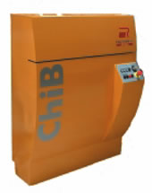 Figure 5: Active fibre launching system “ChiB” Figure 5: Active fibre launching system “ChiB”
Further, the automatic launching prevents operators from lacerations, contamination with splinters and other hazards.
High-dynamic fibre pay-offs
Rosendahl’s fibre launching system “ChiB” and fibre cutting and clamping device works in combination with the high dynamic pneumatically loaded compact fibre pay-off MFA300 or the high speed fibre pay-off MFA500 (Figure 6).
Figure 6: Multi fibre pay-off MFA500
The multi fibre MFA300 is the compact pay-off system for high-end fibre optic cable manufacturing using standard reels. Up to 24 pay-off positions in line are possible enabling the paying-off of up to 12 fibres while setting-up another 12 reels. This is the basis to meet the requirements for continuous production of up to twelve fibre tube designs. The MFA300 is designed for production speeds up to 500m/min and the fibre tension can be adjusted in the range from 30g to 300g with a accuracy of ±10% of the actual set point. The multi fibre pay-off MFA500 is designed for special production requirements like speeds up to 1,000m/min and supporting bigger reel sizes up to 500mm as well as different product design (Fibres, HCS, POF, Simplex, Ribbons).
Launching during start-up, scrap reduction
Up to twelve fibres can be launched automatically at production speed into the production line (Figure 7).
Figure 7: Production with / without automatic fibre launcher and cutter
The application of “ChiB” fibre launcher allows continuous operation, reduced scrap in production and more safety at the buffering process. For continuous operation the machine is designed to be re-loaded during production. The system remains in ready to go
state until the next launching is required. “ChiB” fibre launcher is available for Simplex, loose tube, tight coating and semi-tight coating production lines (Figure 8).
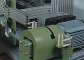 Figure 8: Fibre clamping and cutting device Figure 8: Fibre clamping and cutting device
Charley is the name of the fellow Rosendahl process engineer who demonstrated how to launch fibres at 500m/min. ChiB (Charley in a box) is the electro-mechanical conversion of Charley® patent pending.
Universal fibre optical cable dual reeler DSL1001
The universal semi- or full automatic dual reeler DSL1001 covers the requirements for various cable design in fibre optic cable production (Figure 9). The DSL1001 is geared for 1,250m/min, supports reel sizes from 250mm flange diameter up to 1,066mm (42”) and covers product dimensions from 0.6mm up to 18mm outside diameter including products having aramid yarns as strength members. The combination of the Rosendahl line control system “RIO” together with the automatic fibre launching system “ChiB” for joining fibres and the automatic dual take up “DSL 1001” dramatically increases the production capacity, reduces quality variations and decreases the scrap rate lower than previously achievable.
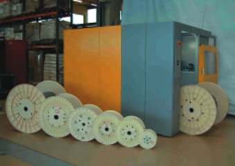
Figure 9: Universal automatic dual reeler DSL1001
In addition, this offers a higher flexibility in improving and exploiting the buffer material colour change sequences in the rapidly evolving production environment.
High-speed SZ-stranding
Rosendahl newest fibre optic SZ-stranding technology ensures improved production speeds whilst keeping a superior product quality. Furthermore high production security is required in order to prevent the damage of the product in case of emergency situations. Figure 10 shows a SZ-stranded product using water swelling tape as binding material in order to achieve the waterblocking of the fibre optic cable.
Figure 10: Reversal point of a proper SZ-stranded product
Improved productivity
In combination with all other items of the SZ-stranding line, such as: driven dancer controlled dynamic tube pay-offs, caterpillars, take-ups, optionally tape pay-offs, jelly filling systems, Kevlar® servers, etc. and finally the high-sophistication of a non-linear driven lay plate SZ-stranding machine SSZ42 or SSZ60 and the special dual cross binding system GSZ290V/R are improving the productivity of the line.
Lay plate SZ-stranding machine SSZ42/60
The patented design of the non-linear driven lay plate SZ-stranding machine (Figure 11) ensures high-dynamic reversals (less than 30msec at ±2,000rpm) by absorbing the energy during “S” or “Z” stranding inside the rubbers. In combination with a “balanced” lay plate design and a adequate tube guiding system. The tension of the stranded elements inside the stranding machine is minimised throughout the complete production speed range .
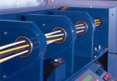 Figure 11: Lay plate SZ-stranding machine geared for 2,000rpm Figure 11: Lay plate SZ-stranding machine geared for 2,000rpm
Dual cross binding system GSZ290V/R
The unique quad cross binding system GSZ290V/R geared for 4,500rpm results in a productivity (binding rate) of up to 9,000 respectively 18,000 (dual yarn cops) lays per minute to the product. Implemented in the final design are a number of special features such as the use of special materials for the flyers and bearings, special designed yarn guiding systems, self balancing binder assembly’s, etc., which ensures the binder can run at high binding speeds for long periods with minimal maintenance. Taking in to consideration the overall design concept of Rosendahl’s SZ-stranding technology. Production speeds are possible up to 150m/min making good quality products continuously on a continuous production basis.
Superior product quality
Accurate, repeatable lay length during “S” and “Z” stranding as well as during the reversal point, low but accurate and symmetric yarn binding tension, the prevention of tube tension increase possibly occurred by the “storage accumulator” effect of the SZ-stranding machine are representing some quality parameters which are ensuring high quality cables with regards to the influence of EFL variations, crush resistance, enhanced temperature cycle test and repeat bending tests.
Symmetrical cross binding directly at the SZ-stranding point
Both, the clockwise and counter clockwise binders are facing each other. Therefore the symmetrical cross binding takes place directly at the SZ-stranding point. The cross binder is furthermore equipped with a core torsion lock which prevents the bending of the SZ-stranded product during SZ.
Keep binding tension in tolerance
Both, the flyer and the binder cob of the cross binder are driven. This allows the adjust of the binding yarn tension by calculating the tension as a relation to the motor load of the binder drive. The figures for the friction and the inertia of the cross binder are evaluated automatically during a self-learning process, the so called auto tune mode.
High-production security
Here after are listed some provisions in the design of the stranding line which ensure production quality over the complete speed range of the machine:
- All pay-offs and take-ups are equipped with storage accumulators;
- Tube pay-offs optionally with lump and cross wrap detection;
- Binding yarn break detectors and yarn cutters for emergency situations;
- Self balancing binder assemblies;
- Selective line ramping for normal production, fast stop and emergency situations.
Conclusion
Based on the experience of more than one decade and by the continuous implementation of the demands of global acting customers, Rosendahl has been able to develop during the last three years the most up to date extrusion and stranding technology. This allows Rosendahl to offer to the market high-productivity, right sized and customised manufacturing systems for a versatile product range of fibre optical cable designs. To offer manufacturing equipment which allows complementary to high speed production the usage of various type of process materials as well as the production of a wide range of cable designs and to improve the Overall Equipment Efficiency (OEE) was the targets for the above mentioned developments.
References
[1] Kertscher, Eberhard: Anlagen zur Glasfaserkabelproduktion. Maria Enzersdorf: Firmenschrift der Fa. Rosendahl Maschinen GmbH 1986.
[2] Rödder, Thomas: LWL Kabel für öffentliche Netze. Nürnberg: Philips Kommunikationssysteme 1989.
[3] Eickholt, Jürgen: Engineering Thermoplastics for high-performance secondary fibre optic jacketing. Marl: Creanova/Huels 1998.
[4] Altmayr, Josef: Fibre optical cable production. Pischelsdorf: IWCS Proceedings 1999, pp. 472-478.
[5] IEC 60794 1-4: Optical Fibre Cables - Generic specification and test procedures: 2001.
|