Introduction
High voltage (HV) and extra-high voltage (EHV) underground
cables commonly are plastic insulated and crosslinked either
in catenary CV-line (CCV) or in vertical CV-line (VCV). There
are some 400 catenary CV-lines and about 50 vertical CV-lines,
or MDCV-lines. Practically all new CV-lines are radiant curing
lines employing water or gas cooling.
The basic process has not changed very much since the introduction
of triple cross-head. One of the few advances has been technology
to produce heavy wall cores in catenary CV-line. Development
in CV-line instrumentation has been more active. An X-ray
system for layer adjustment and gravimetric control of extruder
feeding are examples of measuring units which improve the
operation of CV-line. Today, CV-line automation is based
on a distribution system having programmable logic controllers
(PLCs), operator panels, and process interface connected
via field bus. A curing calculation programme is a vital
part of this automation.
CCV-line versus VCV-line
Roundness and concentricity of the insulated core are essential
for MV, HV, and EHV power cables with XLPE insulation. Specifications
for roundness and concentricity have generally become tighter.
The manufacture of reliably round and concentric layers can
save significant amounts of insulation and semicon material,
and also make further processing phases easier - including
jointing and terminating during installation. Drooping insulation
has limited the production of HV and EHV cores in inert gas
catenary CV-lines. Generally, VCV-line gives better roundness
compared to inert gas CCV-line, but the related building
costs are high. Drooping in an inert gas CCV-line can be
alleviated by reducing insulation viscosity and/or rotating
the core. One solution is to use rotating caterpillars both
before the cross-head and after the end seal. Conductors
for HV and EHV cables are often taped with large sizes of
the Milliken type, and are thus already sensitive to torsional
forces. Round and concentric HV and EHV cores can also be
produced with moderate rotating.
In recent years a significant number of CCV-lines have been
equipped with the entry heat treatment (EHT) system, and
these are now producing heavy-wall cores and giving excellent
results. The system is based on reducing the overall viscosity
of the insulation at the beginning of the CCV-line where
drooping normally takes place. EHT is based on minimising
that part of the insulation that is well over the melting
point but not yet crosslinked (Figure 1). After, the cross-head
conductor cools down the inner semicon and inner parts of
the insulation and increases the supporting diameter. Large
copper conductors, which are normally used with HV and EHV
cores, have high heat capacity per unit length and thus will
effectively cool the insulation.
Additionally, the surface of the core is cooled down by
means of circulating nitrogen after the cross-head and before
the heating zones (Figure 2). Circulation is controlled so
that insulation temperature is at the level of the melting
point on entering the first heating zone.
Figure 1: Melting and crosslinking inside insulation
Figure 2: EHT-system. Cooling circulation is applied after
the cross-head
This short cooling section is followed by high heating,
limited only by the maximum allowable surface temperature
of the core. This minimizes the time during which the insulation
is melted but not crosslinked. Table I shows some roundness
values for cores produced in CCV-line equipped with EHT.
| Conductor
Area |
400mm2 |
630mm2 |
630mm2 |
400mm2 |
800mm2 |
800mm2 |
2,000mm2 |
|
Conductor Material
|
Al
|
Cu
|
Cu
|
Cu
|
Cu
|
Cu
|
Cu
|
|
Rated Voltage
|
132kV
|
220kV
|
400kV
|
132kV
|
161kV
|
400kV
|
220kV
|
|
Cond. diameter Dc
|
23.1mm
|
30.5mm
|
31.4mm
|
23.8mm
|
34.5mm
|
35.5mm
|
55.4mm
|
|
Outer diameter Do
|
77.4mm
|
82.3mm
|
106.5mm
|
72.6mm
|
84.3mm
|
109.1mm
|
107.4mm
|
|
Ratio Do /Dc
|
3.35
|
2.70
|
3.39
|
3.16
|
2.44
|
3.07
|
1.94
|
|
Insulation thickness
|
23.2mm
|
22.6mm
|
32.8mm
|
21.3mm
|
21.6mm
|
32.3mm
|
22.5mm
|
|
Insulation material
|
Normal
|
Normal
|
Low sag
|
Normal
|
Normal
|
Low sag
|
Normal
|
|
Maximum ovality
|
0.9mm
|
0.6mm
|
-
|
0.7mm
|
1.2mm
|
0.7mm
|
1.0mm
|
|
Average ovality
|
0.7mm
|
0.4mm
|
1.3mm
|
0.4mm
|
0.9mm
|
0.7mm
|
0.9mm
|
|
Minimum roundness
|
0.988
|
0.993
|
-
|
0.990
|
0.986
|
0.995
|
0.990
|
|
Average roundness
|
0.991
|
0.995
|
0.988
|
0.994
|
0.990
|
0.995
|
0.991
|
Table I: Some typical roundness values in Maillefer CCV-line
with EHT-system
Maximising line speed
In many cases, however, VCV-line are preferred. Since building
costs for CV-tower are remarkably high, it becomes vitally
important to maximise line speed. Extruders, if correctly
selected, can normally fulfill VCV-line output needs. It
is a question of curing and cooling capacity. To fully utilise
layout possibilities, a pressurised turn pulley is commonly
used in VCV-line to extend cooling length. Chillers for cooling
water can be used, but there is not much more that can be
done to improve cooling capacity.
The situation is different for curing capacity. Inductive
conductor heating can be utilized more effectively by means
of post-heating (“post-heater”). Today the typical
preheating temperature in VCV-line is in the range 60 to
100°C. There are several reasons why preheating temperature
is limited. These include copper oxidation, conductor tape
deformation, moisture-block material deterioration, etc.
The post-heater is located after the cross-head in the pressurised
tube, where the conductor can be heated up without these
limitations. Post-heat temperature up to 180 - 200°C
can be used. This allows a significant increase in line speed
of 20-40%, depending on core and CV-line layout. Figure 3
shows a comparison for VCV-line with and without post-heater.
It should also be observed that much shorter heating length
is needed with post-heater. This length can be used for cooling.
Figure 3: VCV-line with and without postheater. Curves
show conductor temperature and surface temperature. Core
is Cu 1,000mm2 132kV
Preheating 80°C
28m heating + 47m cooling = 75m
total
Speed = 0.83m/min
Inductive Power 2.7kW
Radiant Power 14.7kW |
Preheating 80 °C + Postheating 100 °C
14m heating
+ 61m cooling = 75m total
Speed = 1.15m/min = +39%
Inductive Power 10.4kW
Radiant Power 12.4kW |
Figure 4 shows the inductive coil used for post-heating.
It forms part of a 0.5m long CV-tube. Due to the insulation
and semiconductive layers, coil diameter is large in relation
to the conductor diameter. This of course means rather low
heating efficiency, but becomes negligible in importance
when compared, for instance. to the price of materials.
Figure 4: Inductive coil used with post-heating
Optimisation within process constraints
Even today, core temperature or crosslinking cannot be measured
on-line. Numerical simulation and optimisation of the process,
based on thorough process know-how and connected seamlessly
to CV-line automation, are of vital importance. Simulation
opens a window into CV-line process, showing both core temperature
and crosslinking (Figure 5).
Figure 5: Numerically calculated core temperature inside
CV-tube. Figure shows temperature from cross-head to end
seal. Left side is conductor temperature; right side, surface
temperature
Curing calculation consists of both simulation and optimisation.
The optimisation part uses simulation to find and state the
maximised line speed within given process constraints. Typically,
curing calculation is used as recipe generator for CV-line
automation system.
CV-line automation
An automation system for CV-line consists of PLCs with distributed
process interface, PC-based process supervising unit as operator
interface, and curing calculation as recipe generator. In
a modern CV-line there can be several independent PLCs for
such separate units or functions as line equipment and tube
heating, implemented with Profibus, Interbus, or similar
technology. The process supervising unit (Figure 6) includes
process displays, trends, logging, alarms, and recipe system.
Trends and data logging are of great importance, since abnormal
situations during production can be traced afterwards.
Figure 6: User interface (PSU) of modern CV-line
Achieving savings in materials
Material savings during start-up and production has been
the focus over recent years as a result of reduced profit
margins in the cable business. Accordingly, in CV-line start-up
it is important to reach acceptable process conditions and
core quality as fast as possible. For core dimensions, this
means the use of an X-ray system for centering. In the production
phase it is possible to utilise either an X-ray system or
a gravimetric method, or both. An X-ray system is included
in practically all new CV-lines, and these units have been
installed in many existing lines as well.
Figure 7: X-ray system installed after cross-head
Gravimetric control has also been shown to give significant
material savings. This system is installed on the hopper
of the extruder, for measuring granule flow gravimetrically
and controlling screw speed. X-ray is irreplaceable for centring
and start-up. But for controlling longitudinal variations
also, gravimetric control should be considered.
The Control of contaminants
Dielectric strength of XLPE insulated cables depends primarily
on the smoothness of the insulation-semicon interface as
well as the purity and integrity of insulation. These in
turn depend on material cleanliness, handling, and extrusion.
Cleanliness of extruded insulation material can also be controlled
in-line with an optical cleanliness scanning system. This
is installed between the main extruder and the cross-head
and inspects 100% of the insulation material. Polymer is
flowing between two glass windows. Since molten LDPE is transparent,
possible foreign particles can be seen and recorded. For
large contaminants, size and shape are reported; for small
ones, only the number of particles per category.
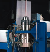
Figure 8: CSS installed in CV-line after insulation extruder
Conclusion
Radiant curing CV-line has not changed very much over the
last two decades. Single-screw extruders, radiant heating,
and water or nitrogen cooling are still used. Even triple
cross-head has been in use for quite some time. Even so,
some clear changes have taken place. HV and EHV cores are
now insulated and crosslinked in catenary CV-lines. Extended
conductor heating is used to improve CV-line efficiency.
Curing calculation has been further developed to better utilise
CV-line capacity. Instrumentation, notably X-ray and gravimetric
systems, is utilised to save material and reduce scrap. And
an X-ray system is already a practical standard.
Maillefer Extrusion Oy
Ansatie 6a B
FIN-01740 Vantaa
Finland
Fax: Int’l +358 9 88 66 57 71
|


