TECHNICAL ARTICLE:
| Rolling for the Production of Plastically Strained Ropes and Strands | ||||||||||||
| By: Veniamin Alexandrovich Haritonov, Director; and Lev Markovich Zaretsky, Research Officer; R&D Department, Magnitogorsk State Technical University - Russia | ||||||||||||
Introduction One of the principal factors in attempted improvement of rope and strand is plastic strain, which permits directed dislocation structure, redistributes longitudinal stress, and enlarges the contact area: between the wires in the strand, between the strands in the ropes of the double lay, and between rope and pulley in the hoist ropes. Extension of the contact area reduces the contact pressure. It also improves aggregate yield and breaking tensions, as well as the plastic properties. Moreover, it enhances the relaxation stability of PC strands. Use of the Monolithic Die Usually plastic strain is imparted to ropes and strands by means of drawing through the monolithic die. Among the benefits of this method is the simplicity of the equipment. It also provides axisymmetric and even-to-length deformation of the rope or strand, and ensures reduction right up to full gauge infill. Drawing through the monolithic die also has several considerable disadvantages. First, it requires large energy consumption to compensate for friction on the stationary walls of the die; and lubricant is pressed out of the deformation centre through the grooves between the wires. Second, the deformation centre consists of separate elements which can move about one another, each having greater height and smaller length. Consequently, deformation is uneven. The high friction reinforces this unevenness, which in turn creates considerable temper, reducing the stress-strain and plastic properties. Sometimes this temper can result in the extra-contact defect known as “lantern”. Third, drawing through the monolithic die compels long and labour-intensive attention to rope dressing. Finally, in reinforcement applications, reduction of the strand results in cohesion retrogression requiring strand cohesion evaluation. In this evaluation method, developed by the present authors, the index that defines resistance to lengthwise movement of strand is 30% lower for cogged strand (with 5% reduction) than that for incoming round-wire strand. Correspondingly, the cogged strand exhibits noticeably lower resistance to lengthwise movement. This means that cohesion can be conserved only by shortening of the lay step, which reduces the stress-strain properties and raises the initial cost. Clearly it would be preferable to use more effective methods of reduction. Drawing through the roller die Drawing through the roller die reduces the amount of energy necessary to compensate for friction owing to joint movement of the rope with the walls of the die. It provides even deformation without lagging of external sections, which may also reduce energy consumption. Energy consumption will drop approximately 20% in comparison with drawing through the monolithic die. But this method does not solve the problem of rope dressing to the die. Nor does this method provide axisymmetric and even-to-length deformation of the rope or strand. The formation of round sections needs an intermediate shaped gauge, which is effective for monolith wares but stimulates the unevenness of separate wire deformation in ropes and strands. This method also requires more complicated equipment. Reduction of ropes and strands can also be obtained by rolling, which addresses the problem of rope dressing to the gauge, at least in principle, and promises 10% lower energy consumption in comparison with drawing through the roller die. But this method requires more elaborate equipment than that for drawing through the roller die. Also, it does not resolve the problem of deformation unevenness. The authors have calculated the mutual dependence of the width of the contact area, which depends on the reduction, and the value of contact stress. Figure 1 shows the dependence of 1x7 round-wire strand with 15.2mm nominal diameter.
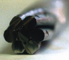
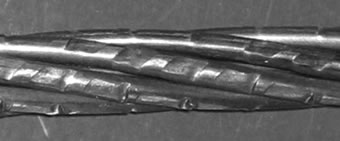
This dependence shows that the preferable reduction of round-wire strands is over the range 2 to 7 per cent. It allows a decrease of 2- to 3.5 times in the contact stress. The further reduction slightly decreases the contact stress, but at the cost of considerable energy consumption. It also results in the creation of wire verges. Consequently, any bend of excess-reduced strand leads to considerable stress-strain degradation because of loading unevenness and large contact stress, caused by line or point contact between the verges of dislodged wires. Reduction of rope and strand is more effective when section infill is incomplete. It permits reduction in one pass and rolling in the round-up groove without intermediate shaped gauge. For high-cohesion of PC strands In addition to the benefits described above, drawing through the roller die and rolling allows the production of strands with the die-rolled section, which creates high cohesion of PC strands. Strands analogous with the die-rolled section are made by the rope lay of wires with the previously die-rolled section. In particular, this method is utilised in PC strands of BS 5896-1980 standard, which can be twisted with the three-sided die-rolled section of the external wires. In spite of high cohesion with the concrete, this construction is not very popular because of poor manufacturability and low stress-strain properties, deriving from the point contact between the wires. In contrast to this method, rolling with the die-rolled section to the external surface of the strand creates good cohesion with the concrete and higher stress-strain properties than in round-wire strand. Particularly, contact stress between the wires of the cogged strand is 10 to 20 times lower then in BS 5896-1980 strand. It is moreover distributed even-to-length of the strand. Figures 2 and 3 show prototypes produced with the die-rolled section of external surface.
Tests on these production prototypes showed higher cohesion than for analogous BS 5896-1980 strand. They also showed higher stress-strain properties than for analogous round-wire strand. But it must be mentioned that longitudinal rolling (and drawing through the roller die) does not allow evenness of deformation and profiling.
Use of the shaped gauge The use of shaped gauge, or the deformation of strand and rope with the shaped section, can raise the unevenness up to unacceptable values. Longitudinal rolling and drawing through the roller die thus have a limited range of applications. It becomes preferable to use linear-screw drawing through the roller die or rolling, to impart length and deformation to the cogged rope or strand. Besides the benefits cited, linear-screw drawing through the roller die and rolling allow the production of strands with the die-rolled section, shaped profile, or some combination of these solutions. It also offers the possibility of reducing ropes and strands of a complicated section. It endows the strands with high-cohesion ability, useful for reinforcing various materials and enhancing its value for PC strands and metal cord manufacture. Conclusion The authors have developed a special stand for use with any type of rope-twisting machine. The stand rotates with the rotor of a given machine, ensuring the constant position of the rollers about the reducing rope or strand. The equipment can be mounted separately, if necessary, and the stand enables work on ropes and strands to be performed outside of the plant. Accordingly, the use of rolling or the analogous process of drawing through the roller die promotes high-quality plastically strained ropes and strands while simultaneously lowering energy consumption. These methods also permit the production of new configurations of rope and strand. The most prospective line of development is linear-screw rolling or drawing through the roller die, which promises maximum quality of any plastically strained rope and strand, and also makes possible the production of a number of new constructions not feasible with current technologies.
|
||||||||||||
|
||||||||||||