Abstract
The EPCAD process is a new method of cleaning and coating metal surfaces using electro-plasma. EPCAD stands for 'electro-plasma cleaning and deposition' and works by establishing a gas and vapour plasma in a layer of bubbles at the surface of the work-piece. The method was invented by two Russian scientists, Dr. V Ryabkov and Dr L. Steblianko and is the subject of various patents 1-4.
|
This paper relates to the use of EPCAD technology to clean and coat steel wire. In cleaning, the wire or wire rod is passed through an electrolytic cell in which the wire is grounded and serves as the cathode, while being sprayed or irrigated with a sodium-based electrolyte (e.g. sodium bicarbonate) which passes through an anode held at high DC voltage (typically 80 to 200V). |
|
Under the right conditions of electrolyte flow and temperature, a plasma is established in a layer of bubbles on the surface of the wire, causing the efficient removal of the toughest scale and all other contaminants. The resulting cleaned surface has a unique texture, which facilitates the bonding of coatings, and becomes passivated (rust-resistant). The paper describes the process, outlining how it works and using electron microscopy to reveal the various processes responsible for the removal of scale and other contaminants. Coating is achieved by the same method but using an electrolyte based on the metal to be coated, for example, zinc sulphate for zinc coatings. Mixed metal coatings can readily be applied using mixed electrolytes provided they are mutually soluble in water.
Introduction
The cleaning and coating of metal objects, including wire, are normally two completely separate processes. As far as wire and rod are concerned, the removal of soil, including mill-scale and patenting scale, is usually carried out by acid pickling. Coating, on the other hand, is accomplished by the hot dipping or electroplating.
Electro-plasma cleaning and deposition (EPCAD) is a new technology by which cleaning and coating can be carried out using the same equipment and, if desired, on-line in a continuous process. Both cleaning and coating are effected by an electro-microplasma established on the surface of the moving wire (or other metal work-piece). Instead of acid, the process uses harmless electrolytes consisting of aqueous solutions of metal salts.
The method is quick, economical and highly effective. In cleaning, it produces a unique micro-rough surface which provides an excellent mechanical key for subsequent coating with metal or plastic. The cleaned surface of steel wire (or other steel work-pieces) is also passivated (rendered rust-resistant) by the process.
Physical basis of the process
The anode is typically held at 80 - 200V DC while the article to be cleaned forms the cathode and is grounded. In the case of a moving wire, grounding is achieved through roller-guides located at each end of the treatment zone. The anode for wire is typically a cylinder or part-cylinder and the wire is guided along the cylinder axis. The gap between the anode and the wire is typically 13 - 16mm.
An electrolyte in contact with the anode is forced through small holes in such a way as to impinge on the wire. Electrical continuity between anode and cathode is either through the liquid streams/jets or, under suitable conditions, through an electrolyte foam caused by the electrolyte boiling at the wire surface. The electrolyte is pre-heated to, say 70°C. For cleaning only, the electrolyte is a sodium salt such as sodium carbonate or bicarbonate. For coating, the electrolyte contains salts of the metal(s) to be deposited for electroplating.
The process operates in an electrical regime in which the current decreases with increase in voltage (sometimes called the "unstable region"). The decrease in a current is due to the increasing resistance in the electrolytic cell due to the formation of a layer of bubbles on the cathodic surface.
These bubbles are created by electrolysis of the aqueous electrolyte, which causes hydrogen to be released at the cathode. Small hydrogen bubbles nucleate larger steam bubbles, producing a 'raft' of discrete bubbles. At this stage most of the voltage drop across the cell occurs across the bubble layer, producing an extremely large potential gradient. This in turn causes electrical breakdown within the bubbles, producing a high temperature plasma.
The plasma, which is confined to the surface of the cathode (wire), creates various effects. When the process is used for cleaning steel these effects are as follows:
1) Thermal shock causing crazing and flaking of the brittle oxide layer(s);
2) Direct chemical reduction of the oxide layer to pure iron;
3) Melting of the oxide layer followed by rapid chemical reduction to pure iron;
4) Melting of a superficial layer of steel leaving a characteristic cratered surface and preventing hydrogen embrittlement;
5) Removal of carbon from a superficial layer resulting in surface passivation;
6) Breakdown and removal of non-oxide surface contaminants.
When the process is used to coat a wire with another metal, the further effect of the plasma is:
7) To project the positive ions of the coating metal(s) at the cathode surface at high velocity, where a thin band of intermetallic compounds may be formed before the coating layer begins to build up at deposition rates of up to two microns per second.
Cleaning patenting scale from wire
We now describe, by the way of an example, the claiming of a 1.3mm diameter steel wire with a heavy, lead-contaminated layer of patenting scale.
| The equipment consisted of a four-inch long cylindrical anode of 3cm internal diameter. The detailed design of the anode is still proprietary, but involves projecting streams of electrolyte to impinge on the wire and establish electrical contact between anode and cathode. The wire was guided along the axis of the cylindrical anode. The electrolyte was a 13% by weight solution of sodium bicarbonate in water and was maintained at a temperature of 73°C. |
|
The DC voltage on the anode was set at 100V and the wire speed at 7.0ft/min. The electrolyte flow rate was increased until plasma was seen to form on the wire, which could be viewed through two viewing ports in the cylindrical anode. Once the flow rate was high enough to produce a stable plasma, the wire emerging from the treatment zone was observed through a magnifier to be virtually clean with a "satin" finish. The degree of chemical cleanness of the wire was subject to sample checks later using the Energy Dispersive Spectroscopy (EDS) facility on a scanning electron microscope. The current being drawn by the anode was recorded.
The speed of the wire was then increased in increments until a speed was reached at which small regions of residual scale could be detected on the emerging wire. This speed and the previous speed (at which the wire was still completely clean) bracket the "critical speed" at which the wire is just rendered completely clean. The two "bracketing" speeds were recorded.
Keeping the voltage at 100V, the electrolyte flow rate was increased to a new level and recorded. The current increased with increasing flow-rate and its new value was noted. The wire-speed experiment was repeated and a new pair of 'bracketing' speeds found. The whole experiment was repeated for a range of electrolyte flow-rates and then again for a series of anode voltages.
Results
From the length L of the anode (in feet) and the critical speed Sc of the wire (in feet per second) we can define a "critical dwell time" Tc as L/Sc (in seconds). This is the time of plasma treatment required to just clean the wire completely. For brevity we shall call this the 'dwell time' dropping the "critical".
When the dwell time is plotted against the power consumption (voltage x current in kW) a single smooth curve results for all flow rates and voltages. An example is shown in Figure 1 where the bracketing speeds have been used to plot two points for each different power consumption (power consumption changes with flow rate and voltage). In Figure 1 the circles represent "clean-wire" points and the squares represent 'not-clean-wire-points'. The curve is drawn between the bracketing points and marks the line of separation between the upper region in which the wire is completely cleaned and the lower region where the dwell time is too short to obtain complete cleaning.
Figure 1: Wire-cleaning parameters
It can be seen that the dwell time required to clean the wire has a minimum in the region of 1.5 to 2.0kW power consumption. The process is most efficient in this range of power supply. At lower power, there is sufficient energy available to clean the wire, while at higher power the wire surface probably re-oxidizes, making good cleaning difficult to achieve. It is clearly important to operate in the high efficiency zone.
These data are for the 4-inch anode. Clearly, the power consumption is proportional to the anode length (ignoring any end-effects). The critical speed of the wire is also proportional to the anode length, since the definitive quantity for any given wire is the dwell needed to get it clean. If we double the length of the anode, we can also double the speed of the wire. This means that, in principle, there is no limit to the speed at which wire can be cleaned. In practice, the treatment zones for high speed cleaning have to be broken into several separate zones (with cooling means between them) to avoid over-heating the wire.
Consideration of the costs of electrical power for the plasma and for handling equipment suggests that the cost of using EPCAD for cleaning wire is highly competitive with traditional methods for most wire and rod products. The degree of cleanness achieved is very high and the wire surface becomes significantly passivated (rust resistance) relative to wire cleaned with acid.
Cleaning mechanisms
To elucidate the mechanism of cleaning, scanning electron microscope pictures were taken of a steel plate (not wire) at different stages of the EPCAD cleaning process. In Figure 2 is shown the first stage of cleaning in which the brittle mill-scale has been cracked or crazed by thermal shock from the plasma, and small pieces of the oxide layer have begun to flake off leaving exposed bare steel (or a lower layer of oxide which itself contains cracks).
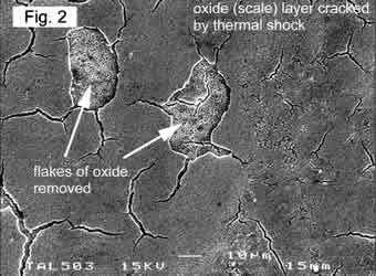
Figure 2: Scanning electron micrograph showing early stages of cleaning
In Figure 3 we show regions of oxide scale that has been converted to alpha iron by chemical reduction ("reduced oxide") and oxide melting before being reduced to iron ("melting oxide"). Figure 4 shows the characteristic 'pockmarked' surface that results from melting of the steel itself after removal of oxide.
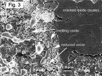
Figure 3: Scanning electron micrograph showing later stages of cleaning
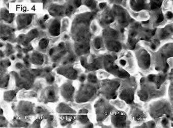
Figure 4: Scanning electron micrograph showing topography of cleaned and passivated steel surface
It is clear that a variety of mechanisms, ranging from the mechanical process of thermal shock and flaking to the chemical process of reduction, conspire to create a rapid cleaning and reducing action. Superficial contaminants like oil, grease and paint are simply burned off during the process.
How clean is clean? This can be assessed using EDS. Figure 5 shows line scans taken on cross-sections of as-received and cleaned samples of steel using oxygen EDS peak. In the as-received condition, there is a 30 micron layer of scale (around 150 counts) on a substrate of steel (around 30 counts; this is a background value and does not mean that oxygen is present in the steel). After cleaning only the background level of counts remains, right up to the surface.
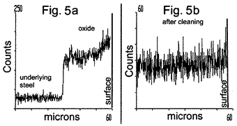
Figure 5: EDS line-scans before and after cleaning a steel surface
Coating
Metal coating can be carried out by using a salt of an insoluble metal in the electrolyte. The example we give here is the deposition of a dense coating of nickel having an average thickness of 18 microns on a 2.59mm diameter steel wire, the wire having been previously cleaned by the EPCAD process as described above.
The anode used was similar in principle to that described above for cleaning, but the electrolyte was an aqueous solution of nickel sulphate containing 5 per cent by weight of nickel. The electrolyte was pre-heated to 70°C. The following parameters were employed:
- DC Voltage: 180V;
- Electrolyte flow-rate: 2.0 litres/min;
- Wire speed: 4.6 ft/min;
- Dwell time: 8.8 sec;
- Run time: 5 min.
It is clear that, depending on thickness, coating dwell-times are normally greater than those for cleaning, the deposition rate for nickel being some 2µm/sec (some metals are deposited more slowly than this). Long dwell-times can cause over-heating of the wire, so that a succession of short treatment zones is preferred, with cooling stations and efficient grounding points between them. The faster the wire is run, of course, the longer the treatment zones can be, but a succession of treatment zones is still required for any but the thinnest coatings.
A sample of the resulting nickel coating is shown in the optical micrograph Figure 6. The coating achieved is dense and well adhered. Its thickness varies between 14 and 22 microns with a roughness Ra of 2.50 ±0.44µm and Rq of 4.57±0.44µm. The adhesion and wear-rate of the coating were measured. Adhesion was 684± 37kg/cm2 and the wear-rate was very low at 3.2x10⁻⁶mm3/mN (this is 1,000 times lower than bulk nickel but this is largely due to the presence of a steel substrate).
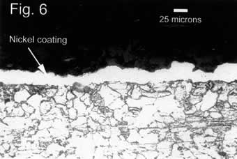
Figure 6: Optical micrograph of steel wire cross-section with an 18µm (average) nickel coating deposited at 2µm/sec using EPSCAD
The coating composition determined using EDS was as follows:
- Nickel: 90.5%
- Aluminium: 1.3%
- Iron: 4.4%
- Zinc: 1.2%
- Silicon: 1.8%
- Other: 0.8%
In EDS it is normal to find some environmental contamination; elements recorded at less than 2% are not necessarily present in the sample itself. The figure for iron, however, is significant and indicates that there is some alloying present between substrate and coating. This is normal with EPCAD which involves the partial melting of the substrate metal and high-speed injection of coating atoms. Clearly, this effect promotes excellent adhesion of coating to substrate.
Conclusion
The EPCAD process is an efficient and cost-effective method of cleaning and coating wire. The examples discussed in this paper involved cleaning and coating steel wire, but the method can be applied to any wire and any form of contamination. The cleaning obtained is of excellent quality; all oxides are removed, along with less tenacious contaminants and the wire surface becomes chemically clean. With steel wire the surface is also passivated, allowing longer exposure to the atmosphere before subsequent coating operations need to be carried out.
EPCAD cleaned surfaces have a characteristic topography that promotes the adhesion of subsequently applied coatings or claddings, whether metal or plastic. Coating adhesion is normally superior to that obtained by conventional coating methods. Smoother surfaces, if required, can be obtained by operating at relatively low voltages. Metal coatings can be achieved using the same equipment/production line as for cleaning but substituting an aqueous salt of an insoluble metal. Providing the metal salts are mutually soluble in water, mixed metal (alloy) coatings can be achieved.
A single line can be operated in which cleaning and coating stations occur in sequence. Indeed, cleaning and coating can be carried out simultaneously by using a 'coating electrolyte' which first cleans and then, once an area of surface has been cleaned, proceeds to coat the exposed substrate metal. However, sequential on-line cleaning and coating produces better results and is easier to control.
References
1. International patent application WO-A-35051
2. International patent application WO-A-35052
3. International patent application WO-A-99/15714
4. International patent application WO-01/09410
About the authors
Edgar Andrews is Emeritus Professor of Materials at the University of London, England. After graduating in Physics in 1953 he worked for Imperial Chemical Industries and The Rubber Producers' Research Association before taking up the Readership in Materials Science at Queen Mary (now Queen Mary and Westfield) College, University of London, in 1963. He set up the Department of Materials in 1968 and became its first Head and Professor of Materials. He has published over 100 scientific papers and books and was for many years a consultant to the Dow Chemical Company and 3M Co. He retired from the University in 1998.
Edward Daigle is responsible for technical development at EPCAD systems LLC. He worked for many years as an engineer in the oil and gas industry and, more recently, became involved in technology transfer from Russia. He was instrumental in bringing the original Russian EPCAD technology to USA.
Christomil C. Popov is carrying out research into EPCAD at Queen Mary and Westfield College, University of London. After taking BSc and MSc degrees at the University of Sofia, Bulgaria, he worked as a Forensic Scientist before moving to London to do research in Materials Science.
|