Introduction
Growing demand for bandwidth, both in datacom and telecom, is boosting the development of 10 Gbit/s applications. This is reflected in the IEEE 10 Gigabit Ethernet (GbE) standard, which includes both Wide Area Network (WAN) and Local Area Network (LAN) applications. The traditional low-cost, short-reach multimode fibre (MMF) solution is maintained in this standard by means of a new, next generation (OM-3 type) multimode fibre in combination with low cost 850nm VCSEL (Vertical Cavity Surface Emitting Laser) sources. The need for greater transmission capacity continues and telecom and datacom operators are expanding and thus exploring new technologies. |
Draka Comteq, a strong and global label in the international market for optical fibre cables, copper cables and communications cables, has recently launched a new 50µm (OM-3 type) multimode fibre, MaxCap, which supports the 10 Gbit/s application. After the successful introduction of the 1Gbit/s HiCap class of multimode fibre in November 1998, the new MaxCap clearly demonstrates that the group is continuing its strong support of multimode fibre applications based on its proprietary Plasma-activated Chemical Vapour Deposition (PCVD) process, a patented technology that makes it possible to create any desired profile. Thanks to the versatility of this technology, it is suitable for making any preform type, multimode or single-mode.
Company profile
In the Netherlands, Draka Fibre Technology has joined forces with partners Draka Denmark, Draka Telekom, NK Cables, and NKF Kabel for regional and international clients. The five companies are now known collectively as Draka Comteq. With their combined product portfolio and global presence, the group provides its customers with cables, innovative cable solutions, and optical fibres. Since January 2002, Draka Comteq has also integrated by six manufacturers of data communication cables: Draka Datacom Cable Technologies (Singapore), Draka Fileca and Draka Foptica (France), Draka Norsk Kabel (Norway), Draka Multimedia Cable (Germany), Draka UK Cardinal Cable (Great Britain) and Helix/HiTemp Cables and Chromatic Technologies (USA). These companies add cabling for data, voice, video, premise wiring for office and home applications in local area (LAN), wide area (WAN), as well as campus networks. Draka Comteq was introduced in 2001 as the marketing label for Draka Holding's copper and optical fibre telecommunications cables. This decision of joining forces is in response to the developing global demands to service the digitalisation and convergence of multiple communications technologies.
Market development of 10Gbit/s
To a very flexible optical medium
In every segment of optical communications, there is evidence of swift growth to higher bitrates. Hardly familiarised with 2.5Gbit/s systems, telecom network operators are already starting with the commissioning of the next generation single wavelength 10Gbit/s systems (STM-64, OC-192), creating a strong need at central offices for low cost, short-reach 10Gbit/s interconnectivity. Datacom WAN and LAN are likewise moving towards 10Gbit/s. For the LAN environment, this development is positively affecting the backbone and taking care of aggregated 100Mbit/s and 1Gbit/s data streams from the horizontal links (copper and optical). For Storage Area Networks (SAN), the pressure on low cost, short-reach connectivity is being fuelled by the extreme growth of Internet data storage.
In all these areas, a low cost, short-reach multimode fibre (MMF) connection is a key solution and one of major importance. This is reflected by the extensive work being performed by several standardisation bodies and forums (e.g. IEEE, Fiber Channel, OIF - Optical Internetworking Forum -, TIA, IEC and IEC/ISO, etc.). These standards have agreed on a solution covering a distance of at least 300 metres, using low cost VCSELs and a new, next generation 850nm laser-optimised MMF. Surveys have shown that the vast majority of building backbones are within this 300 metres distance. An important consideration during the standardisation process was the notion that, this next generation MMF still has to fulfil backwards compatibility to legacy applications, both at 850nm and 1,300nm. This feature makes the next generation MMF a very flexible optical medium.
Low cost multimode fibre solution
The strength of multimode cabling has always been the low cost solution it offers for the short-reach. To determine the lowest cost solution for 10Gbit/s, alternatives have been studied [2]. In this study, solutions shown in Table I were considered:
Table I: solutions considered in which:
- MMF = multimode fibre
- SMF = single-mode fibre
- LX = long wavelength (1,300nm) electronics
- SX = short wavelength (850nm) electronics
- WWDM = Wide Wavelength Division Multiplexing
Figure 1 shows the estimated relative costs associated with each of these alternatives for a building riser backbone at 1GbE and its upgrade to 10GbE. The exact costs will differ in each case, depending on the specific details of the network configuration and cost evolution over time. Electronics include the LAN switch plus installation costs; cabling includes cable, apparatus, jumpers, connectors and installation costs. In each of the cited cases, it is evident that the cost of the electronics far exceeds the cost of the cabling.
Figure 1: Relative cost projection for typical configuration [2]
MMF + WWDM shows the cost of installed (legacy) multimode fibre cabling. At 1Gbit/s, the electronics are cost-effective, short wavelength Gigabit-Ethernet (GbE) devices (1000BASE-SX). Migration to 10Gbit/s requires the use of 1,300nm WWDM (Wide Wavelength Division Multiplexing) electronics, which have the highest projected cost due to the need for multiple lasers, combiners, filters, detectors and a special mode-conditioning patch cord.
SMF shows the projected costs of using single-mode fibre (SMF) for both 1GbE and 10GbE. At 1GbE, the electronics are long wavelength Gigabit-Ethernet devices (1000BASE-LX). For 1GbE, LX (long wavelength electronics) devices are more expensive than SX (short wavelength electronics). Upgrade to 10GbE would allow the use of single channel single mode electronics (10GBASE-LX), that are simpler than WWDM electronics. So the overall solution is less expensive than the MMF + WWDM.
MMF to SMF shows the projected costs of installing a conventional MMF infrastructure and upgrading the system to SMF for 10GbE. In this case, use of SX devices instead of LX at 1GbE more than offsets the cost of the additional SMF cable installation, making this upgrade path less costly than the previous two.
OM-3 MMF shows the projected costs of using a next generation OM-3 MMF cabling system. Since this solution enables the use of single channel short wavelength electronics for both 1GbE and 10GbE, it has the lowest projected cost of the upgrading solutions studied.
Bandwidth performance ensured by DMD verification
Apart from the fibre characteristics, the system bandwidth, generally depends upon the spectral and temporal behaviour of the laser and detector. However for the 10Gbit/s, MMF applications covered by the new 10GbE standard, the system bandwidth limitations are largely determined by the mode distribution launched from the source and the Differential Mode Delay (DMD) behaviour of the multimode fibre. The interaction of a Vertical Cavity Surface Emitting Laser (VCSEL) source with given launch distribution, coupled into an MMF with a certain modal delay structure, represents the effective modal bandwidth. This parameter cannot be specified directly, but is ensured by a limitation of both the power distribution of the VCSEL source and the DMD of the next generation OM-3 type MMF. IEEE has defined a minimum effective modal bandwidth of 2,000MHz.km at 850nm in order to maintain a system distance of 300 metres.
The source power distribution is measured according to standard FOTP-203 or IEC 61280-1-4. For a source coupled to a 50µm MMF, the encircled flux of the VCSEL is specified as:
- At radius 4.5µm: =30% -> source not too small.
- At radius 19µm: =86% -> source not too large.
The next generation OM-3 type MMF is characterised by DMD (FOTP-220 or IEC 60793-1-49). In this measurement, the fibre core is scanned at the entrance using a small spot size and a very short pulse, while the corresponding output pulses are registered consecutively. In this way, the modal delay structure of the MMF is found. Compared with the well-known bandwidth test methods, the DMD test method is capable of giving much more detailed information on the propagation characteristics of the different modes of the MMF. Figure 2 shows an example of the DMD pattern of a next generation OM-3 type MMF at 850nm.
Figure 2: DMD example at 850nm
Using the laser sources indicated above, power is coupled primarily into modes with well-bounded delays, which ensures the minimum effective modal bandwidth.
Fibre characterisation
The DMD requirements for next generation OM-3 type MMF are specified by any one of the following six DMD templates (Table II). Each of these templates consists of both an inner and outer mask.
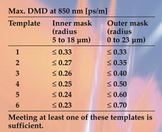
Table II: DMD templates, next generation OM-3 type MMF
Fibres passing template 1 inherently meet the required =1,500MHz.km overfilled modal bandwidth at 850nm. For the other templates, the additional requirement of =1,500MHz.km overfilled modal bandwidth at this wavelength should be met. Some examples of these DMD templates are illustrated schematically in Figure 3, showing the permissible length-normalised time differences between the first leading edge and last trailing edge of the impulse response, plotted versus the radial offset position of the scanning spot size. A trade-off is acceptable between the tightness of the inner mask and the looseness in the outer mask.
Figure 3: Examples of DMD templates at 850nm
In addition, the inner mask (5-18µm) may be positioned anywhere (i.e. floats) within the outer mask (0-23µm). Template 1 with a maximum DMD of 0.33ps/m, in both the inner and outer mask, is known as the "flat mask".
New multimode fibre provides cost-efficient 10Gbit/s premises backbone solutions
To meet these new requirements from telecom network operators, Draka Comteq has recently launched a new 50µm OM-3 type multimode fibre, laser-optimised at 850nm, branded MaxCap, which is suitable for 10Gbit/s applications over 300m. This product fulfils the need for low-cost, short-distance 10GbE applications such as backbones for local area networks (LAN), storage area networks (SAN), and central office connections. These fibres are produced by a proprietary Plasma-activated Chemical-Vapour Deposition (PCVD) process[1], acknowledged world-wide as offering the best core profile accuracy in multimode fibre. On the basis of its PCVD process, Draka Comteq has a leading position in multimode fibre production. In 1999 the company was the first fibre manufacturer to offer 1Gbit/s solutions for 1,000m and 2,000m using multimode fibre (HiCap).
Increasing transmission speeds
The 10Gbit/s application, the backbone of building premises networks and equipment rooms, will support increasing transmission speeds in the horizontal parts of the network. In both copper and fibre, 1Gbit/s bit-rates have become quite common. Although longer backbones do occur, the majority of 10GbE ports are projected for use in business environments with backbones under 300m. There is tremendous pressure for capacity growth in SAN applications (Internet storage data), which explains why fibre channel, the leading SAN solution, will include a 300m 10Gbit/s MMF solution at 850nm. In central offices, demand for low-cost 10Gbit/s connections is exploding due to the upgrade to 10Gbit/s (OC-192/STM-64) in transmission systems.
Two performance qualities
The new Draka Comteq class of MaxCap multimode fibre has been designed to meet the requirements of the new 10GbE standard. It is available in two performance qualities:
- MaxCap 300 supports 10Gbit/s serial transmission at 850nm over 300 metres;
- MaxCap 150 supports 10Gbit/s serial transmission at 850nm over 150 metres.
The former supports 10Gbit/s serial transmission at 850nm, over 300 meters; the latter, the same transmission over half the distance. Draka Comteq offers a whole series of multimode fibre products to support a variety of applications, with bit-rates ranging from multi-Gigabit speeds to legacy 100Mbit/s and lower. Since each network has its own demands, this series of multimode fibre products offers the end-user many possibilities for optimising a network in the most flexible way. These fibres have several excellent features:
- As OM-3 type MMF, MaxCap 300 fully supports 850nm (SX) serial 10 Gbit/s applications over 300 metres. An effective modal bandwidth of 2,000MHz.km, at 850nm under laser launch, is guaranteed by the 850nm DMD performance according to the templates indicated Table III; the overfilled bandwidth at 850nm is =1,500MHz.km.
- MaxCap 150 MMF supports a serial 10Gbit/s application at 850nm over 150 metres. This fibre is characterised by an 850nm DMD flat mask of maximum 0.7ps/m, which, in combination with the same encircled flux criteria for the source as indicated above, guarantees an effective modal bandwidth of =950MHz.km. The overfilled modal bandwidth at 850nm is =700 MHz.km.
- The 1,300nm overfilled modal bandwidth of both MaxCap fibre types will be =500MHz.km, giving strong support to legacy applications. These fibres offer a smooth, low cost migration path for premises backbone cabling from 10Mbit/s up to 10Gbit/s over 300 metres and 150 metres, respectively.
- Just like HiCap MMFs for 1GbE applications, the new MaxCap MMFs offer another cost-saving advantage: they eliminate the need to use special mode-conditioning patch cords for 1,300nm laser based systems such as 1000BASE-LX.
- Draka Comteq has a long history of 50µm and 62.5µm MMF production. The company's multimode fibres feature an excellent microbending sensitivity-reducing coating, which has been specially developed for multimode cabling. This coating is also used for the 50µm MaxCap MMFs, resulting in easy cabling and installation.
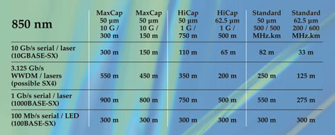
Table III: Draka Comteq MMF support of 850nm Gigabit + 100Mbit/s applications
Table IV: Draka Comteq MMF support of 1,300nm Gigabit + 100Mbit/s applications
HiCap fibres for longest Gigabit-Ethernet link distances
Using its proprietary PCVD process, the company also produces GIMM (Graded-Index Multimode) fibres with the highest profile accuracy available on the market. Typically, several thousand layers are deposited in the core region with each containing well-controlled doping concentrations and thus refractive index values. This number of layers is higher than other fibre processes are able to deposit. Because of adequate process steps in the preform production process, which is focussed on the inner part of the core, the core profile is consequently freed from distortions. This factor has enabled the introduction, at the end of 1998, of an enhanced quality class of laser-certified high capacity GIMM fibres, branded HiCap. These fibres do not require the use of expensive mode-conditioning patch cords in LX (1,300nm) applications. Such a money-saving feature has been confirmed in a series of comprehensive system tests. Figures 4 and 5 offer some examples of Gigabit-Ethernet eye patterns for HiCap fibres, showing perfectly clean eye patterns.
Figure 4: Eye pattern for 500m of 62.5µm standard optimised HiCap fibre, coupled with an 850nm VCSEL (1.25Gbit/s)
Figure 5: Eye pattern for 2,200m of 50µm standard optimised HiCap fibre, coupled with a 1,300nm FP laser (1.25Gbit/s)
Against this background, a number of successful Gigabit-Ethernet system tests have been performed on standard (1,300nm) optimised PCVD HiCap GIMM fibres, with both 50µm and 62.5µm core diameters. Based on these experiments, maximum distances for Gigabit-Ethernet systems are guaranteed for HiCap fibres, as shown in Table V. Further study revealed that the maximum link distances for 62.5µm HiCap fibre, at 850nm, could be increased by 25% to 500m. This improved performance was introduced at the end of last year. The lengths indicated in Table V are the longest Gigabit-Ethernet link distances reported in the industry.
| |
|
SX LX
short wavelength
(850nm) |
Long wavelenth (1,300nm) |
Gigabit-Ethernet |
62.5µm |
220m |
550m |
50µm |
550m |
550m |
HiCap 62.5µm |
before Nov 2001 |
400m |
1,000m |
since Nov 2001 |
500m |
1,000m |
HiCap 50µm |
|
750m |
2,000m |
Table V: HiCap Gigabit Ethernet maximum link distance
Gigabit applications for MaxCap and HiCap multimode fibres
With the new MaxCap multimode fibre, Draka Comteq now offers a whole series of MMF products that support a variety of applications, with bitrates ranging from multi-Gigabit speeds to legacy 100Mbit/s and lower. Since each network has its own demands, this series of MMF products offers end-users the best possibilities for the flexible optimisation of their networks. This is illustrated in Table III (850nm applications) and Table IV (1,300nm applications). Four-channel 10GBASE WWDM applications will run at 3.125Gbit/s per channel. Furthermore, Draka Comteq's HiCap and MaxCap MMF do not require a mode-conditioning patch cord for 1,300nm Gigabit applications.
Standardisation
TIA will standardise this fibre under specification TIA/EIA-492AAAC and IEC will refer to it as A1a.2 type multimode fibre. Within the IEC/ISO premises wiring cabling standard 11801, the 10Gbit/s serial 300-metre option MMF is referred to as OM-3 type fibre.
What is the Plasma-activated Chemical-Vapour Deposition process?
A patented system producing high-quality optical fibres
Because customers are posing ever-higher demands for quality in optical fibres, Draka Comteq products are manufactured according to the company's unique Plasma-activated Chemical-Vapour Deposition (PCVD) process[1] , in which gas in a glass tube is converted with the aid of microwave energy into thousands of thin layers of transparent silica. This technology produces a very high-quality optical fibre with high transmission capacity and minimal signal loss. The high deposition accuracy, the low deposition temperature, the extremely high material efficiency, and the versatility of the PCVD process all promote the production of excellent-quality optical fibres on a large industrial scale.
The deposition efficiency of the PCVD process is extremely high: close to 100% for fluorine and silica. The exhaust gases (or reaction gases) require little additional treatment, except for neutralisation of chlorine gases. From an environmental point of view, the PCVD process shows distinct advantages over others, because the amount of raw materials needed and the production of waste are significantly lower.
The PCVD process
The substrate for PCVD deposition is a silica tube, which is located between a pump and a mass flow controller. A combination of GeCl4 and C2F6 gases, freon gas C2F6, and O2 is injected into the tube. A resonator traverses the tube and introduces microwave energy into this gas mixture. The high microwave energy in the silica tube generates a plasma in which the gases react with one another. The electrons move at a speed equivalent to a much higher temperature (60,000°C) than the ion temperatures (1,200°C), maintained by a furnace over the entire unit. From the reaction between SiCl4 and O2, pure silica (SiO2) is created. The combination of GeCl4 and O2 produces GeO2, a doping material that raises the refractive index in the core region. In this way, a refractive index profile is gradually built up, layer by layer. The deposition takes place directly in a transparent glass layer. Virtually no waste products, such as soot, are formed.
Thousands of thin glass layers
As a characteristic feature of the PCVD process, the microwave energy is transferred to the gas mixture without any energy loss in the silica tube itself. By comparison, other inside-tube processes rely on energy transfer by means of the wall of the substrate tube. In the PCVD process, the travel of the resonator along the tube can be as fast as several metres per minute. This allows the deposition of several thousand very thin glass layers inside the tube, on the order of a micron in thickness. As the gas composition may be changed during each run, the result is a highly accurate refractive index profile inside the core region of the preform and therefore the fibre.
Conclusion
Using its PCVD process, Draka Comteq creates and produces multimode fibres with the highest profile accuracy available on the market. After the successful launch of its HiCap fibre in 1998 and the recent launch of the new MaxCap multimode fibre, Draka Comteq once again underlines its reputation as world leader in MMF products, offering low cost 10Gbit/s short-reach applications, while at the same time supporting backwards compatibility to legacy applications.
References
[1] Van Bergen, Breuls, "PCVD: The Ultimate Technology for Production of High Bandwidth Multimode Fibres", Proceedings IWCS 1998, p.66-71
[2] Kolesar, "Proposed Set of PMDs, Related Specifications and Rationale", IEEE 802.3ae, Interim meeting Ottawa, 23-25 May, 2000
|