Introduction
Davis-Standard Corporation, USA, a division of Crompton and Knowles Corporation, a technological leader in the manufacture of extrusion and blow moulding systems is dedicated and determined to use its resources, talent and imagination to produce the finest equipment world-wide. This article presents an overview of the LAN cable market, crucial points in the manufacturing of LAN cables and Davis-Standard's technical solution to producing the highest possible quality of insulated wire for use in LAN cables. |
LAN cable market overview
North American driven network systems are based upon an architecture that is fed from fibre optic cables and utilise a 8 Wire/24 AWG (4 pair UTP) cable to provide service for riser, horizontal and patchcords. Information technology has progressed significantly and has placed great demands on the copper cable structure and both the signal frequency has increased and the need for lower attenuation and crosstalk.
Modern cable manufacturers have primarily had to learn through trial and error about which process techniques would improve a given performance characteristic of the cable in order to meet the ever-evolving technical specifications. Amidst this rapid evolution of technology and an unprecedented demand for performance cable driven by a strong economy in North America, there has been much turmoil over cable designs (STP, SSTP, UTP, Plenum, Non-Plenum, SFS), a serious lack of raw materials for the North American Plenum Cable Market, and a lack of updated and progressive industry wide bench-marking specifications. See Figure 1.
European countries, such as Germany and France, are using STP or SSTP designs in order to comply with EMC (Electromagnetic Compatibility) directives while LAN designs for North American and N.A. influenced countries such as Ireland and England use primarily a UTP design. There is a shared opinion that as the transmission frequencies increase, the need for shielding or screening increases because the electromagnetic interference increases with frequency, at some stage there will be a point that the EMC may not meet the standards of the FCC (which is what the UTP designs are mostly based on) or that the FCC standards will change to be closer to that of the European Standards (EN-55022 and EN-55024).
Manufacturing technical emphasis
Copper quality
It has been proven that there is a line speed and/or cable specification that will induce Structural Return Loss (S.R.L.) into the wire because the flyer pay-off induces 1 twist per revolution which equates to a cable S.R.L. between 60-100MHz (depending on reel size and how full it is). It has also been discovered that when wire is purchased on a reel, no matter what precautions the wire producer has taken, the copper tends to be unclean, not as round as desired and full of surface imperfections.
|
UTP cable design
SSTP cable design
STP or SUTP cable design
|
In the case of reel pay-off on the insulation extrusion line, most cable producers have gone to one of two routes when producing the higher performance UTP's:
- The use of a driven reel type pay-off instead of a flyer and/or the use of in-line conductor calibrating. With a roll-off type pay-off, the one twist per revolution is eliminated but this process also has a draw-back, depending on production speed, continuous production may not be possible. The in-line conductor calibrating station can be a great benefit to upgrade an existing line as in most cases an immediate improvement on S.R.L. can be achieved;
- The use of a tandem wire drawing machine. The latest generation of wire drawing machines place the final drawing die in the annealing section of the machine which allows much more consistent control of the elongation than if you were to adjust the annealing voltage in order to control wire elongation.
Another positive feature of the new generation of machines is that they include a wire re-heater as an integral part of the machine. Wire temperature is critical so that proper and constant adhesion between the conductor and dielectric is maintained. As a positive progression of technology, digital drives, encoders and PLC based control systems have allowed for better speed regulation and synchronisation which ensures a more consistent copper diameter. This is a step that is critical for LAN cable manufacturing.
Insulation quality
Producing a good and consistent quality insulated wire is a crucial key to the entire LAN cable manufacturing process. Once a means for good quality conductor has been established, it is time to focus on the insulation extrusion line. The key variables that should be adhered to are:
- Very tight manufacturing tolerance on OD of insulated wire (less than 1% of OD, + or -);
- Good adhesion between the conductor and the insulation, as important as the adhesion itself is the consistency of the adhesion;
- Insulation concentricity: it is generally accepted that in order to produce Cat. 5, 90% is the minimum, Cat 5 +, 95%, and in order to meet Anixter Level 7, 97%;
- The relationship of conductor/wire OD must be constant throughout the entire length of cable, the measured parameter is capacitance.
Pairing process
UTP technology has progressed from Cat. 5 beyond mainly by shortening the lay-lengths during the pairing process. The "ripple" effect of this has made machinery manufacturers produce machines capable of higher twinning speed. This is possible thanks to progressive development in bows (more aerodynamic designs decrease drag thus enabling the increase in speed with equal or less wire tension and less HP required). Another way to improve the pairing process is the use of driven pay-offs with tension control for each wire, this reduces the input wire tension and allows higher line speed without further copper draw down.
As discussed in the insulating process, digital DC, servo or vector drives improve the speed regulation and coordination of the pairing machine ensuring that the lay-lengths are very accurate and consistent and that the wire tension is constant and controlled throughout the line.
Perhaps the biggest change in the concept of the pairing process brought about by higher bandwidth LAN cables is the concept of back-twisting one or both of the individual conductors as part of the pairing process. Back-twisting the individual wires is used to compensate for poor eccentricity during the insulating process. The back-twisting essentially "randomises" the capacitive imbalance which in itself is not the best solution, but better than a reoccurring event that happens at the same interval. Since the initial use of back-twisting, most manufactures have found ways to improve the eccentricity of the primary wire (as discussed in the "Insulation Quality" and under "Davis-Standard Solutions") but still use the back-twisting as a means of ensuring consistent production quality instead of a means to attain production quality.
While group twinning is not a new concept, it seems to have gained a great deal of attention and emphasis as a solution for LAN cable manufacturing. For UTP, the most economical approach is to use pairing machines with a separate cabler (2-Step). There does seem to be an unofficial belief that the group twinner is capable of producing a higher quality cable. For shielded and/or taped LAN cables the group twinner is more economical both in investment and in operational costs (because several individual processes are tandemized). All the pairs are shielded with equal tape lay-lengths thus equalising the compression forces which improves cable quality.
Cabling process
The most important part of the cabling process is that you take special care not to undo or damage anything that has been done correctly in a previous process. Single Twist cabling is a better choice for products with tapes or foil wraps.
Jacketing Process
The primary objective for jacketing is to ensure continuous production runs (accumulator with 2 pay-offs on the front end and a dual automatic take-up on the rear end). Typically, the jacket is a very loose, thin wall so on-line wall thickness and eccentricity measurement is a must. As with the cabling process, the objective is to run the cable as fast and efficiently as possible without damaging it.
A consideration for Cat. 5+ cables is in the packaging of the finished cable. In the past, reel-less packages have been used where the cable is coiled and than placed in a box. This excessive bending with a tight radius can degrade the electrical properties and also cause binding, knots and snags as the cable is pulled from the box. To overcome this obstacle, an alternative method of final packaging can be used in-line with jacketing the cable can be run onto small cardboard reels, the reels are then placed in a box for the same type of packaging as previously offered. This can be done using a Davis-Standard SP-24 dual reel spooler in the jacketing line.
Solutions by Davis-Standard for a better insulating process
Conductor pay-off systems
Davis-Standard can offer 3 solutions for feeding the copper wire into the extrusion line, they are as follows:
In-line wire drawing
In-line wire drawing ensures the wire elongation is constant, the OD of the conductor is constant, the wire temperature is constant (which is critical for dielectric to conductor adhesion), and that the surface of the copper is clean and free of surface defects. The use of tandem wire drawing is the only possible choice for high-production speeds (greater than 5,500 FPM). Davis-Standard recommends tandem wire drawing even for applications when Plenum cable is produced (FEP or equivalent insulation) at what is considered a "slow" line speed for tandem lines. This is due to the quality advantage gained by tandem wire drawing. The American company can offer a system with a wire drawing machine and take-up system which has been optimised for the slower productions speeds of plenum insulation and this can be a significant costs savings.
| Another benefit of in-line wire drawing is that with the use of the final drawing die in the annealing area, you can assure very consistent wire elongation and it also gives the user the ability to adjust the elongation properties downward (towards 20%) in order to produce a harder wire which is stronger and less likely to stretch during the pairing process. The use of the final sizing die in the annealing area ensures much better control over the wire elongation than if you were to control it electronically (by adjusting the annealing voltage) because as seen in Figure 2, the annealing curve is very steep in the area of 15-25% elongation and a very small voltage change would have a large impact on the elongation.
The use of a dual flyer pay-off
The second and most common pay-off solution is the use of a dual flyer pay-off, which allows for continuous production from reels. A combination wire preheater/metering capstan is used to heat the conductor and to ensure proper and constant wire tension throughout the extrusion line.
|
Figure 2: Relationship of elongation and annealing voltage
|
A load cell mounted at the exit of the capstan preheater is used and is electronically tied in to the drive/speed controller. Davis-Standard has worked with a preheater manufacturer to develop a specification for a LAN cable preheater in which the preheater manufacturer produces the unit in accordance with Davis-Standard specifications for sheave eccentricity, sheave diameters, bearing types and balancing of the moving parts.
Motorised pay-offs
The third and least common solution would be to use 2 motorised pay-offs with an integrated accumulator system. Due to the low tensile strength of the wire, the accumulators cannot be very long as the tension gain from the sheaves is too great. This is a reasonable solution for plenum insulating lines where the resin keeps the line speed low but for a high speed PE or FRPE type line, it is fairly impractical.
With both of the 2 later solutions, the company recommends the use of a conductor calibration station which uses a wire drawing die to "calibrate" the conductor for size and uniformity as well as eliminating any surface defects. After the die, the conductor is sprayed with heated water to wash any residual drawing compound and run through a series of air dryers.
Extrusion process development
Not only for LAN cable, but for all types of extrusion: Davis-Standard has devoted a significant amount of research and development to the improvement of basic extrusion principles: screw/out-put improvement, melt pressure stability, lower melt temperatures with higher out-puts. This natural process improvement is beneficial to LAN cable primary extrusion because as more stable extrudate outputs are made, this ensures diameter and capacitance stability. The American company has a technical centre which is dedicated to the enhancement of the extrusion process. As part of the technical centre, several highly instrumented extruders with a variety of L/D's utilising the latest polymer analysis equipment.
Eccentricity of primary wire
It is an undisputed fact that with LAN cable, the eccentricity of the insulated wire is extremely important. It is a common belief that to make Cat. 5, the eccentricity must be 90% or greater, for Cat. 5 + or Cat. 6, 95% and to meet the latest Anixter specification for UTP Cat. 7, 97% or greater. To ensure that these manufacturing specifications are met and held, Davis-Standard uses a fixed centre crosshead made with extremely tight manufacturing tolerances. The wire producer must also employ the discipline to verify or "calibrate" the tooling set prior to its use to ensure that the tip and die are properly matched and that the tooling does not have excessive wear. When the crosshead is removed from the extruder for cleaning or tooling changes, it is recommended that upon re-installation, the crosshead be levelled and aligned to ensure it is on the wire centre-line.
| The latest development in crossheads, primarily targeted at the 95% and higher eccentricity, use a micro adjustment for the die. Crossheads simply cannot be made with any tighter manufacturing tolerances and still be assembled and disassembled. The micro die adjustment allows the cable producer to move the die with extreme precision and accuracy in order to gain that last 1-2% of eccentricity (see Figure 3).
|
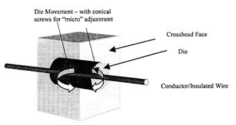
Figure 3: Crosshead eccentricity
|
Quick colour change of stripe
The current EIA/TIA specification for UTP states that as long as the bunched lay-length is a certain length, then there is no need for bandmark or stripe identification of the neutral (white) wire paired with the coloured wire. This specified lay-length is always longer than the actual lay-length that is needed in order to meet electrical specifications (for UTP) but depending on the cable customer or distribution centre, there is a need for identifying the neutral or uncoloured wire in the pair.
Davis-Standard recommends the use of an extruded longitudinal stripe which has the same colour as that of the coloured pair. For UTP there are only 4 colours and if the production is planned properly, the cable producer runs the 4 base colours in succession (no stripe) than changes to a neutral or uncoloured base and runs the 4 different stripe colours in succession. Since the stripe colour must be changed 3 times to balance an equal length of the coloured wires, a system of quick-colour-change for the stripe has been devised so that the line does not have to be stopped and has a negligible amount of scrap when changing stripe colours.
The system uses 2 vertical stripe extruders, 1 in the stand-by position with the upcoming colour and 1 in the process with the current stripe colour. External to the crosshead is a diverter valve that, when the colour change occurs, routes the running extruder to the purge position and routes the purging extruder to the process. A picture of the stripe extruders can be seen in Figure 4.
LAN cable capstan
The American company has refined the design of their multi-pass cooling capstan for copper telephone primary wires in order to ensure that no periodicities in the dielectric be induced from capstan vibration or miss-alignment. The capstan features precision aircraft bearings, drums which are manufactured to a eccentricity of no more than 0.001" T.I.R. (normal capstan drums are 0.010" T.I.R.), the drums once installed are both statically and dynamically balanced to ensure vibration free operation. Another feature is to mount the motor on a base separate from the capstan, this eliminates motor induced vibration. |
Figure 4: Quick colour change (stripe) system |
The latest feature designed into the capstan is the ability to align the drums on-the-fly with the wire line. Poor alignment of the line from crosshead to the capstan can cause erratic eccentricity and OD of the wire because it does not run through the crosshead die parallel to the die hole(it will "dog-track"). The entry drum (which is a cantilevered shaft) is mounted on a bearing assembly which may be adjusted forward and backward with a set screw. Once the capstan is aligned properly upon installation of the line (Davis-Standard recommends the use of a laser for alignment) the wire is strung through the capstan and the line is run at a slow speed. With the mounting screws loose, the you are then able to adjust the capstan until the wire is in the most true running position. Periodically as the drums wear, you can re-align the capstan to ensure that it is consistently in the best alignment possible (see Figure 5).
Figure 5: LAN cable capstan
Instrumentation system
Davis-Standard recommends a comprehensive suite of instrumentation. That monitors: wire tension, conductor diameter/ovality, conductor wire temperature, hot diameter/ovality, cold diameter/ovality, cold capacitance (for foamed dielectric and hot/cold capacitance system is recommended), lump/neckdown in insulation, dielectric voltage capacity (must distinguish between pin-hole and bare-patch) and eccentricity. The system can control based on diameter or capacitance and must have the ability to analyse the capacitance and diameter signal in order to determine periodic fluctuations in the insulated wire. This will relate to S.R.L. in the cable. |
|
Conclusion
Davis-Standard offers technical know-how for the LAN cable extrusion process. In addition to the machinery designs, the company has a proven track record of providing high quality extrusion systems to cable manufacturers of LAN and other communication type cables. By purchasing extrusion equipment from a proven source, the cable producer can be assured that the equipment will be able to produce top quality cable with the shortest start-up period and learning curve possible.
Bibliography
1. Harrington, J. P. "Parameters Effecting the High-Speed Production of Cat. 5 / Cat. 6 Communication Cable, In Particular in the Pairing and Laying up Process". May 1998.
2. Cabelle, R. "Cat. 5+ and Cat. 6 LAN Cables, The World-wide Market Situation and New Trends" Wire Technology International. Vol. XXV, N°. 3
3. Guader, E. and Montusclat, C. "Developments in Cat. 5/6 Cable Manufacture" Wire Technology International. May 1997
|