TECHNICAL ARTICLE:
| Electrical Resistance Measurement of the Cords of Copper and Aluminium | ||||||||||||
| By: AESA S.A, Switzerland | ||||||||||||
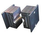
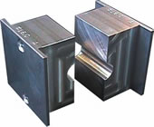
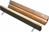
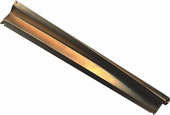
Introduction Over the past 20 years, the Swiss company AESA successfully commercialised a resistance bridge allowing to perform very accurate measurements of the conductor directly on stranding machine(s), without cutting samples. This world-wide known know-how allowed the cable manufacturers to save substantial amounts of raw material, especially for copper stranded conductor products. Using its expertise and technology for this application, AESA is now in position to propose to its wide circle of customers a new generation of resistance bridges type 8135. This new equipment allows now to make highly accurate measurements on medium and large size aluminium (conductor) strands. A measuring unit for aluminium conductors Whereas resistance-per-unit-length measurements are generally unproblematic on copper conductors, they can be prone to significant error and uncertainty, sometimes even hazardous on an aluminium strand, especially if taken on cut sample lengths. Experience shows that a standard 8130 system may not give consistently satisfactory precision on large-section aluminium cords. This is because of uneven current distribution among the strands in the cord layers: when aluminium is exposed to the air, a very thin layer of insulating aluminium oxide forms on the surface, and this causes unpredictable variations in the radial conductivity between strands. The main goal of the 8135 unit is to propose a set-up which puts the above mentioned trouble right, by taking into account that the bridge has to be placed on a stranding machine, this avoiding to cut samples. However and thanks to its design and conception, it can also be used to measure samples that have been previously very carefully prepared. The 8135 system implements a specially tested cable grip method that locally breaks down the insulating oxide layer on the strands without damaging the (cord) conductor. Pressure is applied by gradually varying the differential pressure along four radii spaced at approximately 90° intervals over a sufficiently long length. The geometrically varying pressure profile ensures good contact across the strands in the outer layer and among the inner layers, which are arranged in an inverse helix configuration. Down the line, the solution to the measurement problem consists in a provisory deformation of the strand's geometry. To avoid permanent damage of the cable Because very substantial grip forces are required (up to several tonnes for large-diameter - cords - conductor), the progressive-deformation grips are specially shaped to reduce stress at the grip ends and thus prevent any risk of permanent damage to the cable. Following a test, the (cord) conductor resumes its usual shape naturally under the effect of simple reeling and unreeling operations in the subsequent process, so that no difficulty is experienced with fitting the insulation. As indicated above, the grip force is high. It is provided by a hydraulic system, each grip having the property to move symmetrically to the strand under test. A high-pressure hydraulic pump (max. 720 bars), fitted with a pressure gauge, applies pressure simultaneously to three cylinder blocks. The pressure gauge is graduated in applied force. Each pair of grips is driven by the same pump and, when measuring samples, a valve system allows to tighten the grips one after the other. The operator can refer to a chart indicating experimentally-determined optimum force values for different types of strands, and can check to make sure that resistance readings no longer vary with further increase in pressure. The use of rings In addition to the main grips, the machine uses auxiliary rings precisely fitted to the cord circumference, to ensure good current distribution in the outer layer for further enhanced precision. These interchangeable rings are insulated from the machine casing but electrically connected together, to equalise potentials and ensure good contact across the strands in the outer layer. The required pressure force is also provided by the hydraulic system driving the main jaws.
The wide range of performed tests demonstrated that these auxiliary rings are only required for cords larger than 300mm_ and only when measuring aluminium. In this case, a set of auxiliary rings is required for each type of produced strand (round and sector-shaped). For strands smaller than 300mm, the pressure applied by the main jaws is sufficient. In some particular cases such as sector-shaped, preformed sector-shaped cords or cords which are assembled in one single and same direction, It is required to use main jaws which are geometrically adapted to the cord under test, this to avoid any mechanical damage on the cord surface. These jaws are manufactured on demand and based on drawings provided by the customers. In this case, the auxiliary rings also need to be adapted to the special shape of the cords.
What type of jaws can be used The smaller cords requiring a moderate tightening force are measured using reducing teeth-shaped or V-shaped jaws. The use of these reducing jaws is summarized in the following frame:
Also designed for copper strands The 8135 resistance bridge can obviously also be used for strands made of copper. In this case, the required tightening force is reduced to a minimum (around 50 bars) and auxiliary rings are not required at all, whatever the cross-section of the measured cord.
A manual V-shaped mechanism allows to maintain the (cord) conductors in the centre (d) during the displacement of the main grips and the auxiliary rings until the cord under test is properly tightened. This mechanism is particularly helpful when measuring cut samples.
|
||||||||||||
|
||||||||||||